Electronic Circuit Design
For our electronic circuit design, we separate the circuits into different boards. We have a total of 7 different boards, consisting of an IR circuit board, a power distribution board, a breakout board for E128, a motor control board for the collection roller and tray, 2 motor control board for the driving motors, and a limit switches circuit board.
Power Distribution Board
Description
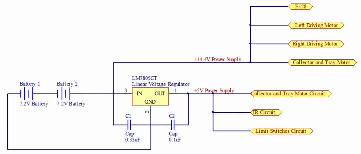
We used two 7.2V batteries from Tower Hobbies in series to provide a 14.4V power supply. The 14.4V power supply will be used to power the 2 driving motors, the collector motor, the tray motor and the E128. The 14.4V is also passed through a LM78L05ACZ linear voltage regulator to provide us with a constant 5V supply that will be used to power the Collector and Tray Motor Control circuit, the Infra-Red detector circuit and the limit switches circuit.
We used two 7.2V batteries from Tower Hobbies in series to provide a 14.4V power supply. The 14.4V power supply will be used to power the 2 driving motors, the collector motor, the tray motor and the E128. The 14.4V is also passed through a LM78L05ACZ linear voltage regulator to provide us with a constant 5V supply that will be used to power the Collector and Tray Motor Control circuit, the Infra-Red detector circuit and the limit switches circuit.
IR Signal Detection Detector
Description
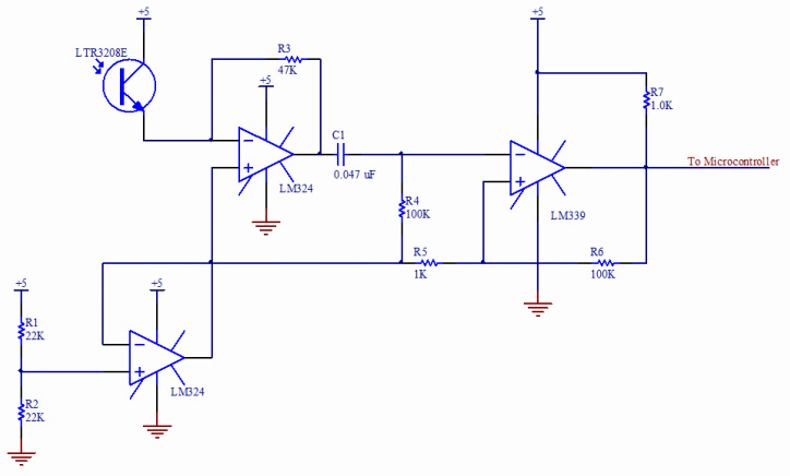
Since we wanted to filter out the low frequency drift from the output of the trans-resistive circuit, the signal output from the trans-resistive circuit is passed through a high pass filter. The cutoff frequency of the high pass filter is calculated to be
Since we wanted to filter out the low frequency drift from the output of the trans-resistive circuit, the signal output from the trans-resistive circuit is passed through a high pass filter. The cutoff frequency of the high pass filter is calculated to be
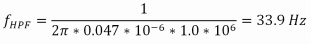
Since the lowest frequency of the infra-red signal is 50 Hz, the above high pass filter is therefore sufficient to filter off the low frequency drift. In addition, since the PWM frequency for the motor control is chosen to be 5 kHz, which in the frequency domain is distinctly separated from the frequency of the infra beacon signal, the PWM would not contribute to any false detection of the infra-red beacon signal.
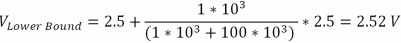
The lower bound of the hysteresis voltage band implemented using the comparator is given by
The lower bound of the hysteresis voltage band implemented using the comparator is given by
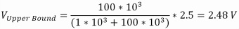
The upper bound of the hysteresis voltage band implemented is given by
Driving Motor Board
Description
We were required to use the two supplied Maxon motors to move our robot around the playing field. We used the supplied motor driver boards, which use a high current TLE5206 H-Bridge to switch the high current required for this low resistance motor.
For the driving control, we used the drive-coast method of driving the two motor, with a pin controlling the speed of the motor using PWM, while another pin controls the direction of rotation of the motor.
Ball Collector \ Ball Unload Tray Motor Board
Description
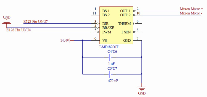
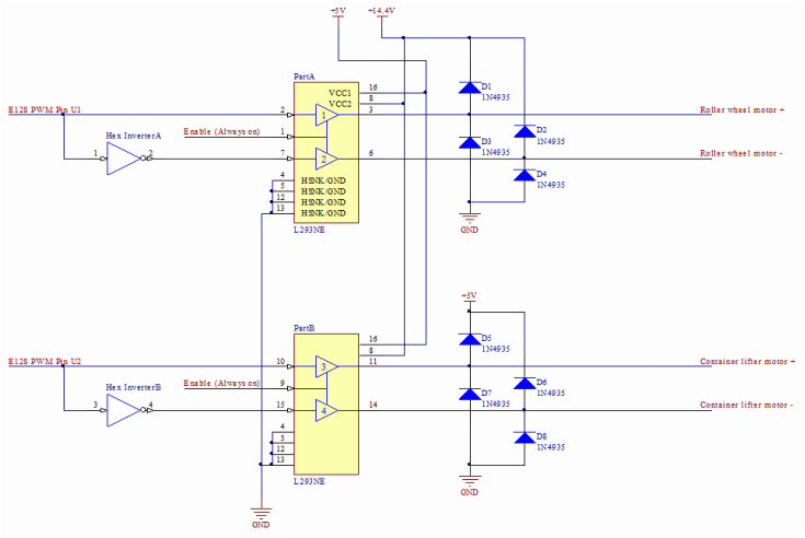
For the collector and the container lifter motor circuit, we used a locked-antiphase driving mode.
For the collector and the container lifter motor circuit, we used a locked-antiphase driving mode.
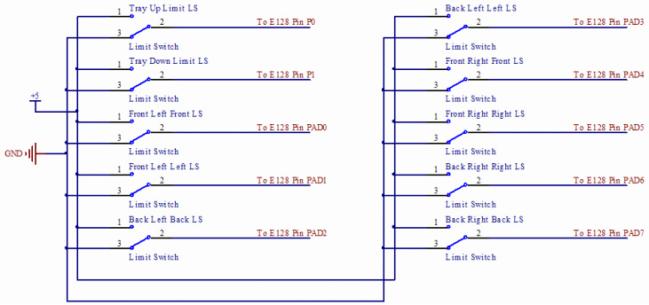
Bumper and Tray Sensor Circuit
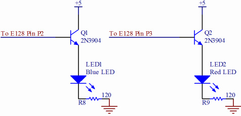
Team LED display circuit
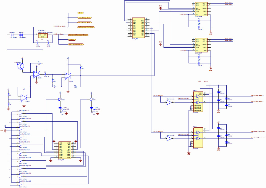
Overall circuit
E128 Pin Table
| JP6 Pin Label | JP6 Pin No. | Use | JP5 Pin Label | JP5 Pin No. | Use |
| NC | 1 | GND | 1 | ||
| PU7 | 2 | Right Driving Motor Direction | PS2 | 2 | |
| PU6 | 3 | Left Driving Motor Direction | PS3 | 3 | |
| PT0 | 4 | PP2 | 4 | Blue LED | |
| PT1 | 5 | PP0 | 5 | Upper Tray Limit Detector | |
| PT2 | 6 | PAD0 | 6 | Front Left Front Bumper Sensor | |
| PT3 | 7 | PAD1 | 7 | Front Left Left Bumper Sensor | |
| PT4 | 8 | PAD2 | 8 | Front Right Front Bumper Sensor | |
| PT5 | 9 | PAD3 | 9 | Front Right Right Bumper Sensor | |
| PT6 | 10 | GND | 10 | ||
| PE0 | 11 | GND | 11 | ||
| NC | 12 | PAD7 | 12 | ||
| NC | 13 | PAD6 | 13 | ||
| PE1 | 14 | PAD5 | 14 | Back Right Back Bumper Sensor | |
| PT7 | 15 | Beacon Detector | PAD4 | 15 | Back Left Back Bumper Sensor |
| PE7 | 16 | PP1 | 16 | Lower Tray Limit Detector | |
| PU0 | 17 | Left Driving Motor PWM | PP3 | 17 | Red LED |
| PU1 | 18 | Roller Motor PWM | PP4 | 18 | |
| PU2 | 19 | Collector Box Motor PWM | PP5 | 19 | |
| PU3 | 20 | GND | 20 | ||
| PU4 | 21 | Right Driving Motor PWM | |||
| PU5 | 22 | ||||
| GND | 23 | ||||
| NC | 24 |
